INTRODUCTION
2.1 BLOCK DIAGRAM
2.1.1 HELMET SECTION
2.2 BLOCK EXPLANATION
POWER SUPPLY:
A regulated power supply is very much essential for several electronic devices due to the semiconductor material employed in them has a fixed rate of current as well as voltage.

The device may get damaged if there is any deviation from the fixed rate. The AC power supply gets converted into constant DC by this circuit. With the help of a voltage regulator DC, the unregulated output will be fixed to a constant voltage.
The circuit is made up of linear voltage regulator 7805 along with capacitors and resistors with a bridge rectifier made up of diodes. From giving an unchanging voltage supply to building confidence that output reaches uninterrupted to the appliance, the diodes along with capacitors handle elevated efficient signal convey.
As per Indian standard, the supply through the mains is 230V, 50Hz AC. For this project, the power requirements are +5V and +12V dc voltage levels.
MICROCONTROLLER − PIC16F876A :
The micro controller controls all the functions of other blocks in this system. The micro-controller takes or reads data from the sensors and controls all the functions of the whole system by manipulating these data.


The alcohol sensor, PIR, and the helmet sensing switch are directly connected to the microcontroller. The microcontroller receives data from these sensors and it gives digital data corresponding to the output of the sensors.
The microcontroller gets power only if the helmet is worn. That additionally checks the output of alcohol sensing elements whether alcohol is present or not. If the condition of alcohol is traditional then the microcontroller communicates to the RF transmitter.
PIR:
Pyroelectric or Passive Infrared Sensor (PIR) are tuned to detect IR wavelength which only emanates when a human being arrives in their proximity. This sensor is added just to make sure that the person is wearing the helmet.
It is connected to the microcontroller. The sensor detects the presence of humans and sends corresponding data to the controller.

MQ3 (Alcohol sensor):
MQ-3 gas detector (alcohol sensor) is suitable for detecting alcohol content from the breath. So it can be placed just below the face defense and above the additional face protection. The surface of the sensor is sensitive to various alcoholic concentrations.

This alcohol sensing element is connected to the microcontroller. It detects the alcohol from the rider’s breath and sends corresponding data to the microcontroller.
HELMET SENSING SWITCH:

RF TRANSMITTER:
The direction from the microcontroller according to the outputs of the various sensors and helmet sensing switch is to be transmitted from the helmet section to the bike section. For this purpose, the RF transmitter is used.

RF RECEIVER:
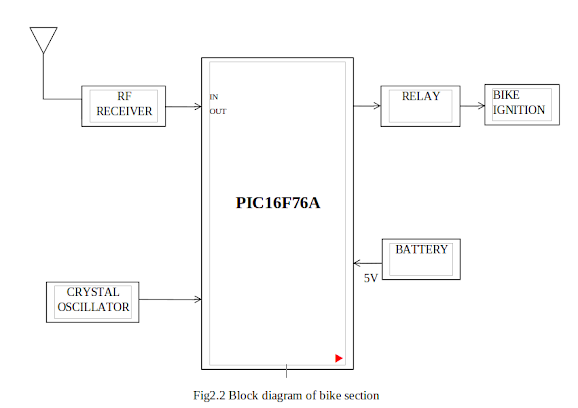
The data from the transmitter is received by the RF receiver and is transferred to the controller.

CRYSTAL OSCILLATOR:
The crystal oscillator is an electronic oscillator circuit that uses the mechanical resonance of a vibrating crystal of piezoelectric material to create an electrical signal with a precise frequency. This frequency is commonly used to keep track of time to provide a stable clock signal for the circuit and to stabilize frequencies for radio transmitters and receivers.

RELAY:
A relay is an electrically operated switch. The relay works according to the output of the microcontroller. It is connected to the bike ignition system.


